Below example shows TA in two subsequent slots. First slot uses old TA value, new slot uses new TA value as indicated by TA command.
| FR | SCS | TAoffset | Old timing advance | TA command | New timing advance | |||
| NTA,offset | time | NTA_old | time | TA | Δ time | |||
| 13 μs | 273.4 μs | -8.1 μs | 265.4 μs | |||||
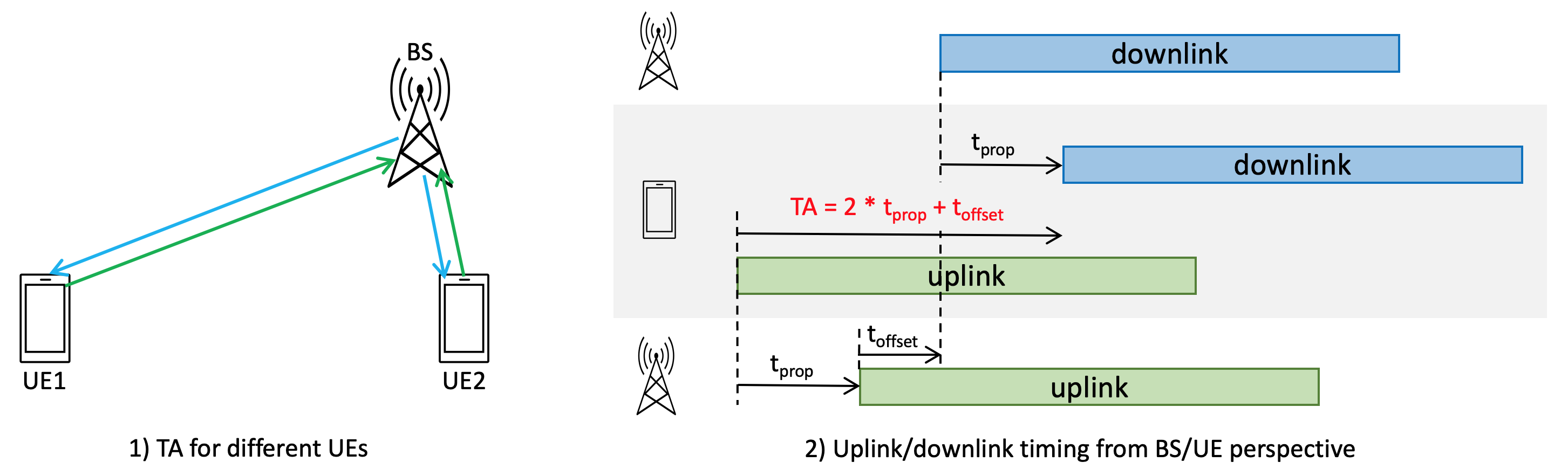
Timing advance (TA) is used to control the uplink transmission timing of individual UE. It helps to ensure that uplink transmissions from all UE are synchronized when received by the base station.
Uplink frame number i for transmission from the UE shall start TTA = (NTA + NTA,offset)·Tc before the start of the corresponding downlink frame at the UE.
Figure below illustrate the concept of timing advance, and the uplink/downlink timing at both BS and UE sides.
- UEs closer to BS has shorter propagation delay, and hence smaller timing advance.
- UEs further awyay from BS has longer propagation delay, and hence larger timing advance.
- TA shall account for the round trip propagation delay, hence 2 · tprop. In addition, it also includes a timing offet toffset = NTA,offset · Tc. The purpose is for an TDD base station to activate its transmitter after an uplink frame.
- Seen from UE side:
- The reference point for the UE initial transmit timing control requirement shall be the downlink timing of the reference cell minus (NTA + NTA,offset · Tc), which is TA.
- The downlink timing is defined as the time when the first detected path (in time) of the corresponding downlink frame is received from the reference cell.
- Seen from BS side, the time difference between an uplink radio frame and the corresponding downlink radio frame is toffset, which is the same for all UEs attached to it. The propagation delay is already compensated at UE side by TA.
- NTA for PRACH equals 0.
Note: Tc = 1 / (480kHz · 4096) = 0.509 ns
How to decide NTA,offset
A UE can be provided a value NTA,offset of a timing advance offset for a serving cell by n-TimingAdvanceOffset in ServingCellConfigCommon or ServingCellConfigCommonSIB for the serving cell. The value can be 0, 25600, or 39936 for FR1. If the UE is not provided n-TimingAdvanceOffset for a serving cell, the default value of NTA,offset is set as 25600 for FR1. For FR2, the value is fixed at 13792, and hence needs not to be signaled to UE. NTA,offset is defined in Table 7.1.2-2 of TS 38.133:
Table 7.1.2-2: The Value of NTA,offset| Frequency Range | Coexistence with LTE | Duplex mode | NTA,offset | NTA,offset·Tc |
|---|---|---|---|---|
| FR1 | No | FDD | 25600 | 13 μs |
| TDD | ||||
| Yes | FDD | 0 | 0 μs | |
| TDD | 39936 | 20 μs | ||
| FR2 | No | TDD | 13792 | 7 μs |
How to calculate Timing Advance (TTA)
, where
Toolbox: Timing advance (TTA) calculator
- Input:
- TA: timing advance command: initialized based on MSG2 (12 bits), updated based on MAC CE (6 bits).
- NTA,offset: FR1: based on n-TimingAdvanceOffset, can be 0, 25600 (default), or 39936. FR2: 13792 fixed.
- Output:
- TA adjustment step size: for each unit value change in TA (+1 or -1), the corresponding change in timing advance and cell coverange.
- NTA: equals TA·16·64/2μ
- Timing advance correspond to TA: NTA·Tc
- Cell coverage correspond to TA: NTA·Tc·3e8/2
- Time allowed for base station to activate transmitter: NTA,offset·Tc
- Total timing advance value: TTA = (NTA + NTA,offset)·Tc
| FR | SCS | TA adjustment step size | TA | FR1 NTA,offset | TTA | |||
|---|---|---|---|---|---|---|---|---|
| time | distance | NTA | time | distance | NTA,offset·Tc | |||
| FR1 | 15 kHz | 520.83 ns | 78.13 m | 3938304 | 2.00 ms | 300.5 km | 13.0 μs | 2016.1 μs |
| FR1 | 30 kHz | 260.42 ns | 39.06 m | 1969152 | 1.00 ms | 150.2 km | 13.0 μs | 1014.6 μs |
| FR1 | 60 kHz | 130.21 ns | 19.53 m | 984576 | 0.50 ms | 75.1 km | 13.0 μs | 513.8 μs |
| FR2 | 60 kHz | 130.21 ns | 19.53 m | 984576 | 0.50 ms | 75.1 km | 7.0 μs | 507.8 μs |
| FR2 | 120 kHz | 65.10 ns | 9.77 m | 492288 | 0.25 ms | 37.6 km | 7.0 μs | 257.4 μs |
Toolbox: TA command effective time calculator
For a timing advance command received on uplink slot n and for a transmission other than a PUSCH scheduled by a RAR UL grant, the corresponding adjustment of the uplink transmission timing applies from the beginning of uplink slot n+k+1 where .
- Input: minimum SCS for DL and UL
- Output:
- NT,1 is a time duration in msec of N1 symbols corresponding to a PDSCH processing time for UE processing capability 1 when additional PDSCH DM-RS is configured
- NT,2 is a time duration in msec of N2 symbols corresponding to a PUSCH preparation time for UE processing capability 1 [6, TS 38.214]
- NTA,max is the maximum timing advance value in msec that can be provided by a TA command field of 12 bits
- is the number of slots per subframe
| SCSDL | SCSUL | N1 | NT,1 | N2 | NT,2 | NTA,max | k | k+1 | |
|---|---|---|---|---|---|---|---|---|---|
| 2 slot | 14 sym | 1.00 ms | 12 sym | 0.43 ms | 1.00 ms | 6 slot | 7 slot |
Note:
- Tsf is the subframe duration of 1 msec
- N1 and N2 are determined with respect to the minimum SCS among all configured UL BWPs for all uplink carriers in the TAG and of all configured DL BWPs for the corresponding downlink carriers.
- For μ=0, UE assumes N1,0=14 [6, TS 38.214].
- Slot n and are determined with respect to the minimum SCS among the SCSs of all configured UL BWPs for all uplink carriers in the TAG.
- NTA,max is determined with respect to the minimum SCS among the SCSs of all configured UL BWPs for all uplink carriers in the TAG and for all configured initial UL BWPs provided by initialUplinkBWP.
- The uplink slot n is the last slot among uplink slot(s) overlapping with the slot(s) of PDSCH reception assuming TTA = 0, where the PDSCH provides the timing advance command and TTA is the value of Timing Advance.
- If two adjacent slots overlap due to a TA command, the latter slot is reduced in duration relative to the former slot.