Rectangular wave and sinc wave
To understand the basics of OFDM, let's start with the Fourier tranform pair of a rectangular function and a sinc function:
- Rectangular function:
- Sinc function: , with
- The Fourier tranform of x(t) is X(f), as can be seen from below:
- Because , the minimum positive f that satisfies X(f) = 0 is , where equals the duration of the rectangular function.
This toolbox shows the relationship between a time domain rectangular signal and a frequency domain sinc signal. Note the inverse relationship between the time domain window length and the frequency domain zero-crossing points.
- : the first zero-crossing frequency
- : window length of the rectangular.
| Hz, Window length: 0.0667 second | |
| Time domain: rectangular signal | Frequency domain: abs(sinc) signal |
|---|---|
Generate OFDM signal from sine waves
Below is what we know:
- The Fourier transform of a sine (or cosine) wave is the impulse response: the Fourier transform of is:
- The Fourier transform of a rectangular wave is a sinc wave. The first zeross-crossing point of the sinc is , where τ is the window length of the rectangular wave.
- Truncate the cosine wave within a window (multiply with a rectangular function), its Fourier transform is the sinc wave, shifted in frequency domain by f0 which is the frequency of the cosine wave.
The idea behind OFDM is to sum multiple sine waves with frequencies of and fixed duration of . In frequency domain, each windowed sine wave corresponds a sinc wave centered at , with null-points at . I.e., every two sinc waves are orthogonal in frequency domain, there is no inter-carrier-interference (ICI).
Toolbox: OFDM from sine waves
This toolbox demostrates a 64-point FFT with subcarrier spacing of 15kHz. The OFDM symbol duration is 1/15K = 0.067 ms. It contains 4 subcarriers at different frequency positions, which are controlled by k0 to k3.
Note: this example is just to demonstrate the orthogonality and the different frequency components of the OFDM signal. Normally, an OFDM signal will be created using IFFT instead.
| k0 = k1 = k2 = k3 = | |
| Time domain: | Frequency domain: |
|---|---|
Cyclic Prefix (CP): what and why
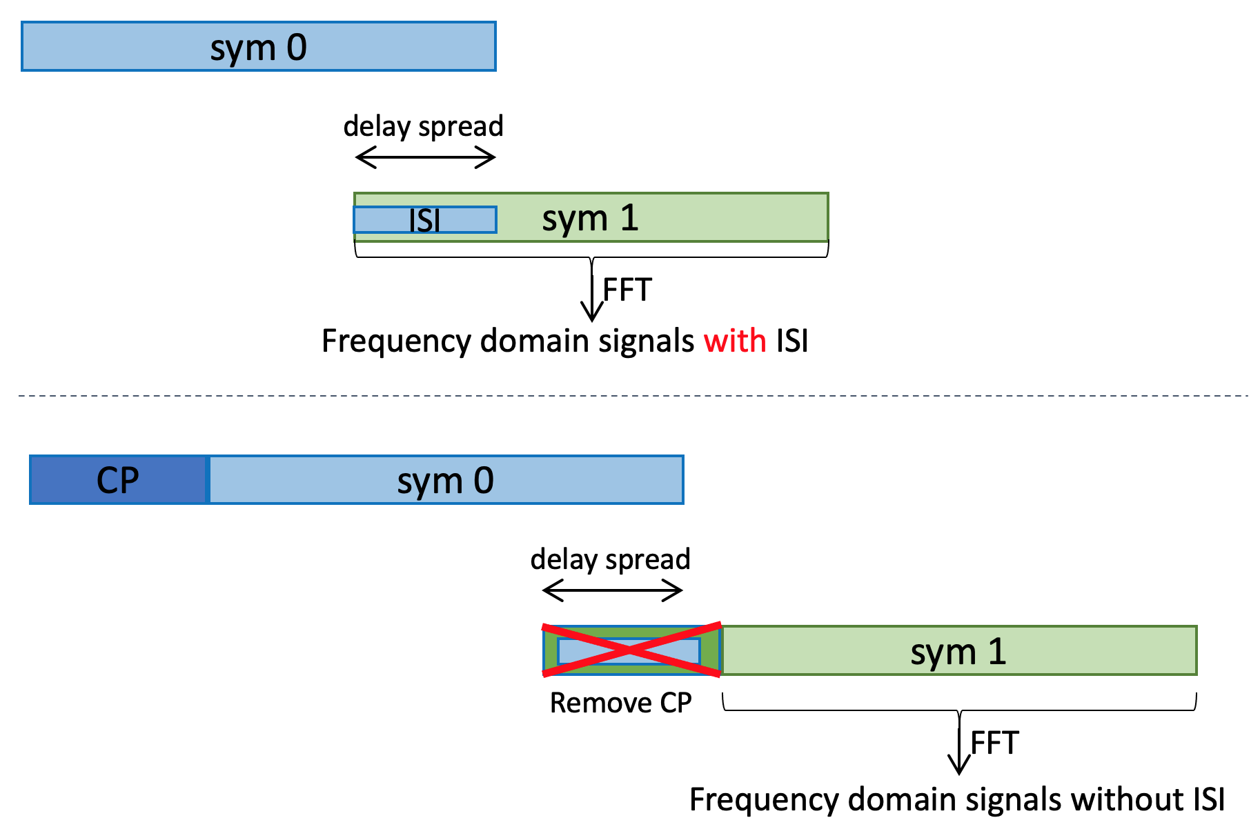
When the OFDM signal go through a time dispersive channel, it gets spreaded in time domain. Thus, if two OFDM symbols are sent back to back, the former symbol will interfere with the latter one. This is commonly known as the Inter-Symbol-Interference (ISI).
The Cyclic Prefix (CP) is a guard time made up of a replica of the time-domain OFDM waveform. The purpose of CP is to combat ISI and inter-carrier-interference (ICI):
- The length of the cyclic prefix shall be longer than the delay spread of the channel. Thus, the receiver can discard part of the received signal, which contains interference from the previous one -- ISI is eliminated.
- The orthogonality among the sub-carriers in frequency domain shall still be maintained -- no ICI.
- CP can be use for other purposes, e.g. to detect the symbol boundary (by correlating first part of the symbol and last part of the symbol).
- If a silence guard period is used instead of CP, that will increase the Peak to Average Power Ratio (PAPR), hence the signal may suffer more from RF impairments.
Figure below shows the impact of using CP (the bottom subplot) to remove the inter-symbol-interference.
OFDM with RF impairments: clipping, non-linear PA, phase noise
RF impairments will reduce the orthogonality of OFDM subcarriers, causing inter-carrier-interferences.
- clipping and non-linear PA: causes harmonics of the frequency components. Thus, the frequency response of one subcarrier will overlap with its neighboring ones.
- phase noise: the frequency response will spread in frequency domain. The sinc wave will not have zero-power points.
This toolbox demostrates the impact of RF impairments to OFDM signal.
- A 64-point FFT with subcarrier spacing of 15kHz is assumed, i.e., 66.7 us.
- Only two sub-carriers are considered. Having more sub-carriers will make the figures hard to read.
| Time domain | Frequency domain | |
|---|---|---|
Clean signal, no impairments:
| ||
Clipping:
| ||
Non-linear PA:
| ||
Phase Noise:
|
Generate OFDM signal using IFFT
Let's take a look at the N-point IDFT equation:
- This IDFT process achieves the frequency shift and the summation as illustrated in the demo above. Thus, we can first create the frequency domain signal, then convert to time domain using IFFT.
- An N-point IFFT converts N frequency domain subcarriers into time domain. When the sub-carrier spacing is , the OFDM symbol duration is , and the minimum sampling rate is .
A live-example of using IFFT to generate OFDM signal in 5G NR can be found at OFDM in NR.