UE performs Radio Link Monitoring (RLM) on active DL BWP of the Primary serving cell (PCell) of the Master Cell Group (MCG). If the UE is configured with a Secondary Cell Group (SCG), then the UE also monitors downlink radio link quality on the active DL BWP of the Primary SCG Cell (PSCell).
Note:PCell and PSCell are collectively known as SpCell (Special Cell).
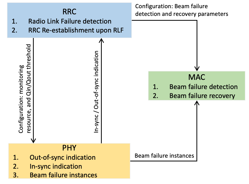
Functional split of physical layer, MAC layer and RRC layer:
- Physical layer: monitors the DL radio link quality, sends measurement results to upper layers.
- MAC layer: beam failure detection and recovery.
- RRC layer: configure PHY and MAC layer; radio link failure detection and RRC-establishment.
Radio link monitoring can be done based on different Radio Link Monitoring Reference Signal (RLM-RS) resources, as configured by base station throughput RRC message in RadioLinkMonitoringConfig:
- SS/PBCH Blocks (SSB), or
- Channel State Information Reference Signals (CSI-RS), or
- a combination of SSB and CSI-RS
If base station does not provide RadioLinkMonitoringRS, UE uses the Reference Signals (RS) provided for the active Transmission Configuration Indicator (TCI) states for the Control Resource Sets (CORESET) for PDCCH reception. If the active TCI state for PDCCH reception includes two RS, the UE expects that one RS has QCL-TypeD, and will be using this RS for radio link monitoring.
The UE is provided either a CSI-RS resource configuration index, by csi-RS-Index, or a SS/PBCH block index, by ssb-Index. The UE can be configured with up to NLR-RLM RadioLinkMonitoringRS for link recovery and radio link monitoring. From the NLR-RLM RadioLinkMonitoringRS, up to NRLM RadioLinkMonitoringRS can be used for radio link monitoring depending on a maximum number Lmax of candidate SS/PBCH blocks per half frame, and up to 2 RadioLinkMonitoringRS can be used for link recovery procedures:
| Condition | # max SSBs per half frame Lmax | # configured RLM RS NLR-RLM | # used RS for RLM NRLM | # used RS for link recovery |
|---|---|---|---|---|
| 4 | 2 | 2 | 2 |
| 8 | 6 | 4 | 2 |
| FR2 | 64 | 8 | 8 | 2 |
Ref: descriptions from 3GPP TS 38.213 clause 5
The downlink radio link quality of the primary cell is monitored by a UE for the purpose of indicating out-of-sync/insync status to higher layers. The UE is not required to monitor the downlink radio link quality in DL BWPs other than the active DL BWP on the primary cell. If the active DL BWP is the initial DL BWP and for SS/PBCH block and CORESET multiplexing pattern 2 or 3, the UE is expected to perform RLM using the associated SS/PBCH block when the associated SS/PBCH block index is provided by RadioLinkMonitoringRS.
If the UE is configured with a SCG and the parameter rlf-TimersAndConstants is provided by higher layers and is not set to release, the downlink radio link quality of the PSCell of the SCG is monitored by the UE for the purpose of indicating out-of-sync/in-sync status to higher layers. The UE is not required to monitor the downlink radio link quality in DL BWPs other than the active DL BWP on the PSCell.
A UE can be configured for each DL BWP of a SpCell with a set of resource indexes, through a corresponding set of RadioLinkMonitoringRS, for radio link monitoring by failureDetectionResources. The UE is provided either a CSI-RS resource configuration index, by csi-RS-Index, or a SS/PBCH block index, by ssb-Index. The UE can be configured with up to NLR-RLM RadioLinkMonitoringRS for link recovery procedures, and for radio link monitoring. From the NLR-RLM RadioLinkMonitoringRS, up to NRLM RadioLinkMonitoringRS can be used for radio link monitoring depending on a maximum number Lmax of candidate SS/PBCH blocks per half frame , and up to two RadioLinkMonitoringRS can be used for link recovery procedures.
If the UE is not provided RadioLinkMonitoringRS and the UE is provided for PDCCH receptions TCI states that include one or more of a CSI-RS:
- the UE uses for radio link monitoring the RS provided for the active TCI state for PDCCH reception if the active TCI state for PDCCH reception includes only one RS
- if the active TCI state for PDCCH reception includes two RS, the UE expects that one RS has QCL-TypeD and the UE uses the RS with QCL-TypeD for radio link monitoring; the UE does not expect both RS to have QCL-TypeD
- the UE is not required to use for radio link monitoring an aperiodic or semi-persistent RS
- For Lmax=4, the UE selects the NRLM RS provided for active TCI states for PDCCH receptions in CORESETs associated with the search space sets in an order from the shortest monitoring periodicity. If more than one CORESETs are associated with search space sets having same monitoring periodicity, the UE determines the order of the CORESET from the highest CORESET index.
A UE does not expect to use more than NRLM RadioLinkMonitoringRS for radio link monitoring when the UE is not provided RadioLinkMonitoringRS.
Values of NLR-RLM and NRLM for different values of Lmax are given in Table 5-1.
Table 5-1: RLR-RLM and NRLM as a function of maximum number Lmax of SS/PBCH blocks per half frame| Lmax | NLR-RLM | NRLM |
|---|---|---|
| 4 | 2 | 2 |
| 8 | 6 | 4 |
| 64 | 8 | 8 |
For a CSI-RS resource configuration, powerControlOffsetSS is not applicable and a UE expects to be provided only 'noCDM' from cdm-Type, only 'one' and 'three' from density, and only '1 port' from nrofPorts.
If a UE is configured with multiple DL BWPs for a serving cell, the UE performs RLM using the RS(s) corresponding to resource indexes provided by RadioLinkMonitoringRS for the active DL BWP or, if RadioLinkMonitoringRS is not provided for the active DL BWP, using the RS(s) provided for the active TCI state for PDCCH receptions in CORESETs on the active DL BWP.
In non-DRX mode operation, the physical layer in the UE assesses once per indication period the radio link quality, evaluated over the previous time period against thresholds (Qout and Qin) configured by rlmInSyncOutOfSyncThreshold. The UE determines the indication period as the maximum between the shortest periodicity for radio link monitoring resources and 10 msec.
In DRX mode operation, the physical layer in the UE assesses once per indication period the radio link quality, evaluated over the previous time period against thresholds (Qout and Qin) provided by rlmInSyncOutOfSyncThreshold. The UE determines the indication period as the maximum between the shortest periodicity for radio link monitoring resources and the DRX period.
The physical layer in the UE indicates, in frames where the radio link quality is assessed, out-of-sync to higher layers when the radio link quality is worse than the threshold Qout for all resources in the set of resources for radio link monitoring. When the radio link quality is better than the threshold Qin for any resource in the set of resources for radio link monitoring, the physical layer in the UE indicates, in frames where the radio link quality is assessed, in-sync to higher layers.