- v: velocity [m/s]
- fc: carrier frequency [MHz]
- τrms: RMS delay spread [ns]
| v = fc = τrms = | ||
| Wavelength | 0.3 meter | |
| Max Doppler shift | 100 Hz | |
| Coherence bandwidth (corr > 0.9) | 0.444 MHz | |
| Coherence bandwidth (corr > 0.5) | 4.444 MHz | |
| Coherence time (corr > 0.5) | 4.23 mili-sec | |
In radio communication, multipath is the propagation phenomenon that results in radio signals reaching the receiving antenna by two or more paths. Causes of multipath include atmospheric ducting, ionospheric reflection and refraction, and reflection from water bodies and terrestrial objects such as mountains and buildings.
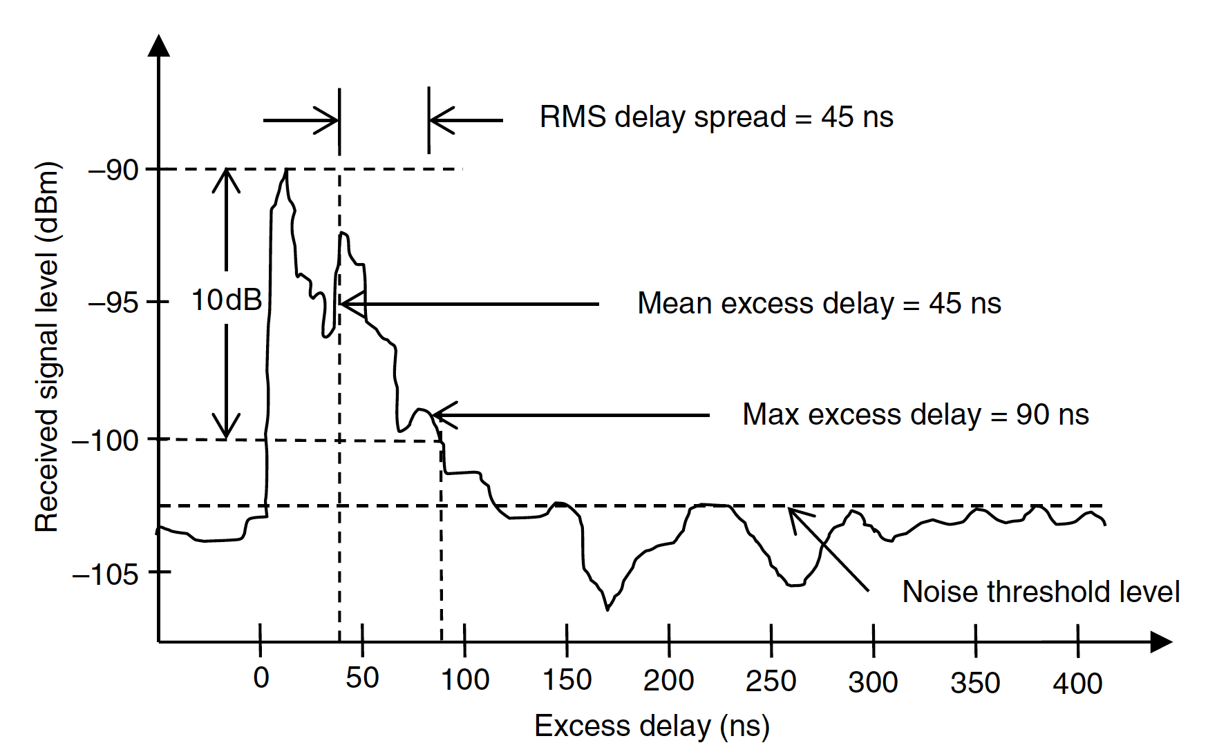
Power delay profile used to describe a multipath channel. It gives the intensity of a signal received through a multipath channel as a function of time delay. Many important properties can be derived from the power delay profile:
- Maximum delay spread : the total time interval we can receive the signals with high energy. A high value of τmax means a highly dispersive channel.
- Root Mean Square (RMS) delay spread : the RMS value of the delay profile, which is used to calculate the channel coherence bandwidth.
The multipath channel is modeled as a linear Finite Impulse Response (FIR) filter. The impulse response of the multipath channel iswhere denotes the amplitude of a multipath component at time t, is the Dirac delta function, and N is the number of multipath components. An example of multipath is shown below.
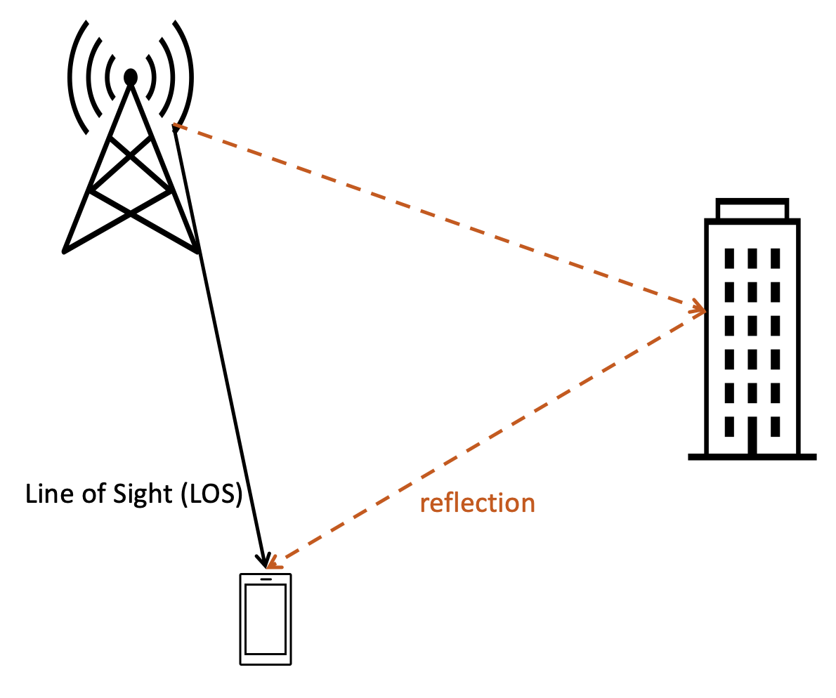 An example of multipath with two composing signals
An example of power delay profile is depicted below [ref]:
Doppler frequency
Doppler shift is the change in frequency of a wave in relation to an observer who is moving relative to the wave source. It is named after the Austrian physicist Christian Doppler, who described the phenomenon in 1842. The Doppler shift is calculated as followswhere
- m/s is the speed of light
- λ is the wavelength of the wireless signal, fc is the carrier frequency.
- v is the speed of the terminal in m/s, θ is the angle of arrival with respect to the direction of the terminal.
- If the terminal moves in the same direction of the signal (away from transmitter), θ = 180°, and
- If the terminal moves in the opposite direction of the signal (towards the transmitter), θ = 0°, and . This maximum Doppler shift is denoted as fm.
Coherence bandwidth
Coherence bandwidth is a statistical measurement of the range of frequencies over which the channel can be considered "flat", or in other words the approximate maximum bandwidth or frequency interval over which two frequencies of a signal are likely to experience comparable or correlated amplitude fading. Coherence bandwidth is inversely proportional to the rms delay spread τmax. A larger rms delay spread means the channel has more frequency domain selectivity. The coherence bandwidth equals:
Coherence time
coherence time is the time interval over which a channel impulse response is regarded as not varying.
The coherence time (Tc) is inversely proportinal to the Doppler spread. For correlation > 0.5:
Depends on the chherence time and the duration of the symbol, the wireless channel can be classified as:
- Fast fading, if the symbol duration is greater than the coherence time. Or
- Slow fading, if the symbol duration is less than the coherence time.
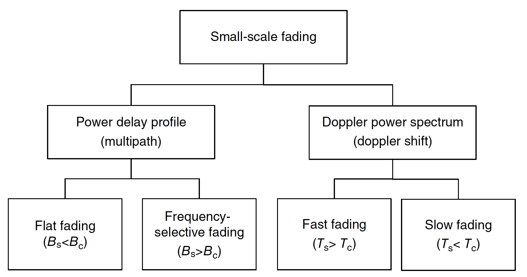 Types of small scale fading [ref]